


The chosen housing is a 19'' standard housing with one height unit
(44 mm / 1.75'') und 280 mm (11'') depth, which I bought at Meyer-Elektronik
(see appendix B.2 on page ![[*]](/images/latex2html/crossref.png) ).
The whole housing consists of sheet steel except the 3mm thick aluminium
frontplate.
).
The whole housing consists of sheet steel except the 3mm thick aluminium
frontplate.
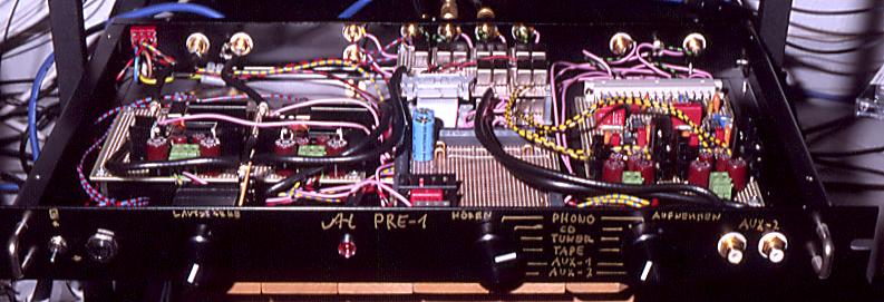
The housing is equipped with gold plated RCA jacks (good quality, DM 5.- each) which are electrically isolated. The jacks of one of the line level inputs were mounted on the front plate. This allows an easy connection to external sources without fumbling around at the backside of the equipment.
A front view of the preamplifier
is in figure 5.1 on page .
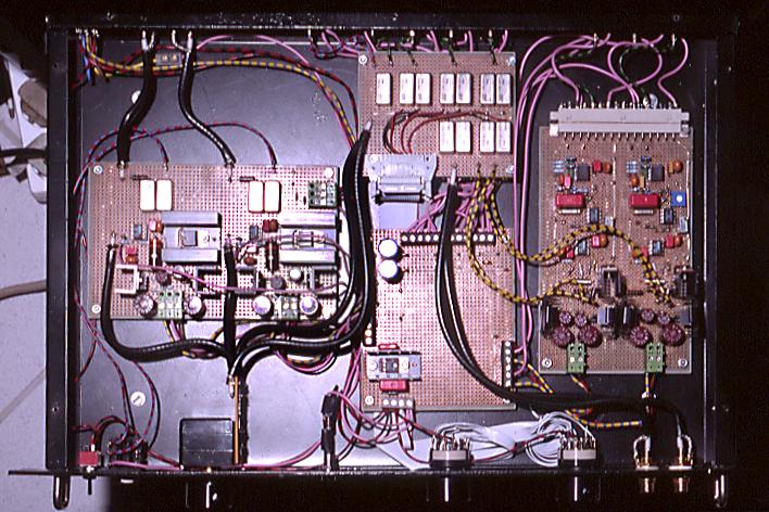
As I had no possibility to produce real pcb's I used doublesided experimental pcb's with solder points in european format (100 mm x 160 mm). The solder points on both sides have no electrical connection. Both channels of the line level stage including the voltage regulations were easily mounted on one such pcb. It was also possible to mount both channels of the phono preamplifier including the voltage regulations on one such pcb, but there was no space left. The electrical connections were done by soldering thin bare wire across the solder points. For the ground connections I used 1 mm silver coated wire.
All ground connections meet at the central point on a separate pcb. I used separate connections for signal ground (SGND) and power supply ground (PGND) to prevent crosstalk of spikes on the power supply ground into the signal ground. This is very important for the phono preamplifier.
The top view of the preamplifier
is in figure 5.2 on page . On the left
hand side is the line level PCB and on the right hand side the phono
PCB. In the middle is the ground PCB which includes the 12V power
supply for the twin input relais PCBs seen above..
![\includegraphics[%
width=1.0\textwidth]{pre1-front_tex.ps}](img87.png)
![\includegraphics[%
width=1.0\textwidth]{pre1-top_tex.ps}](img88.png)