


Placing a humming and LF emitting lines transformer close to a phono preamplifier is definitely not a good idea. Therefore the power supply is located in its own housing which should be placed some distance away from the preamplifier housing. However, the power supply regulation should be placed as close as possible to its sink. Long distances4.1 should be strictly avoided.
I decided to put the lines transformer and the big reservoir capacitors
into an external housing. The power supply regulation is then separate
both for line level stage and phono stage and left and right channel
as well. This means that we must build the ![]() supply voltage
regulation four times.
supply voltage
regulation four times.
A 120 VA toroidal transformer feeds two electrolytical capacitors
of 15 mF each via a 25 A rectifier bridge. Each diode within the rectifier
bridge is bridged by a 100 nF capacitor to get rid of fast transient
spikes. For the same reason both 15 mF capacitors are bridged with
6.8 ![]() F foil capacitors.
F foil capacitors.
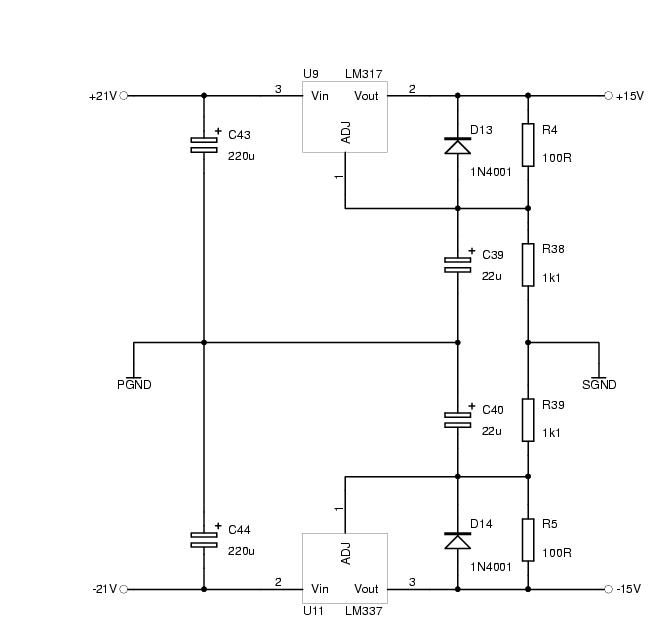
A high qualitiy voltage regulation must be built using high quality parts. It is however no longer necessary to use discret semiconductors as there are now very good integrated voltage regulator ciurcuits available. I chose the adjustable regulators LT1085 (positive) and LT1033 (negative) which are compatible to LM317/LM337. The standard fixed voltage regulators of the 78xx and 79xx series produce much higher noise and have worse ripple suppression, although you can find those even within highend preamplifiers (Bryston 25 BP).
![]() and
and ![]() determine the positive output voltage, while
determine the positive output voltage, while
![]() and
and ![]() determine the negative voltage.
determine the negative voltage. ![]() (and
(and
![]() ) works as an AC short regarding the adjustment input of
the voltage regulator which improves the ripple suppression by about
20 dB.
) works as an AC short regarding the adjustment input of
the voltage regulator which improves the ripple suppression by about
20 dB. ![]() (or
(or ![]() ) leads the discharging current of
) leads the discharging current of ![]() (or
(or ![]() ) in case of an output shortcut away from the adjustment
input, thereby preventing the destruction of the voltage regulator.
) in case of an output shortcut away from the adjustment
input, thereby preventing the destruction of the voltage regulator.
![\includegraphics[%
width=1.0\textwidth]{power_sp_tex.ps}](img86.png)